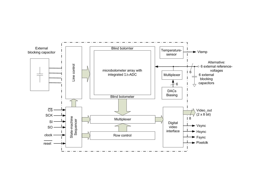
Fraunhofer IMS has developed an innovative readout circuit (ROIC= read out integrated circuit) for uncooled infrared sensors that converts the resistance of the microbolometer directly into a 16-bit signal. Commercial solutions of readout circuits can only reach a digital resolution of about 8 to 12-bit, or use an analog readout of microbolometers so that the analog/digital conversion has to be performed with external components. The high digital resolution of the IMS solution results in considerably higher dynamics that can be reached without saturation effects or deterioration of the temperature resolution. That’s why uncooled infrared sensors of Fraunhofer IMS reach dynamics of ΔT = 300 K while typical commercial solutions are specified to only ΔT = 100 K and therefore result in overload or underload.
Other advantages of the Fraunhofer IMS solution for readout circuits of microbolometer arrays are integrated reference voltage generation as an “Easy-to-Use” concept and circuit measures for noise reduction.The microbolometer array is being read out by parallel ∑Δ-ADCs that are placed homogeneously under the array. In the process the resistance value of a certain number of microbolometers is being converted directly into a 16-bit signal through a ∑Δ-ADC in a multiplex principle. So-called “blind microbolometers” that reduce the temperature sensitivity through technological measures are placed around the active microbolometer array. These can be used for compensation of the environment temperature dependence of uncooled infrared sensors. The 16-bit image signals are lead into the digital video interface via a multiplexer. A programmable sequencer controls the readout process in which every ∑Δ-ADC is chosen using a line and column control block. The readout of the microbolometer array follows the “rolling shutter” principle in which the microbolometer is read out line by line via the field of view from top to bottom. The configuration of the sequencer is performed with an SPI interface (SCK, SI, SO) and a chip-select-signal (CS). The digital video interface offers in addition to the 16-bit image signals for synchronization signals for use in camera electronics. The width of the video interface is reduced through the division of the 16-bit video data into two 8-bit lines. A digital and an analog temperature sensor measure the temperature of the uncooled infrared sensor and can be used for TEC-less operation. The readout circuit of the uncooled infrared sensor needs an analog supply voltage (Vdda = 3.3 V) and two digital supply voltages (Vdd = 3.3 V and Vdd2 = 1.8 V). For the configuration of the ∑Δ-ADC six reference voltages are needed. Besides the use of external reference voltages, all six reference voltages can be produced internally by means of digital-analog converters to reduce the required circuitry of the camera electronics. In addition to the reset signale and the SPI configuration signals, the readout circuit of the uncooled infrared sensor just needs a digital clock signal from which the frame rate is deduced.
The readout circuits are manufactured in the in-house clean room using the automotive certified 0.35 μm CMOS technology onto 200 mm wafers.
