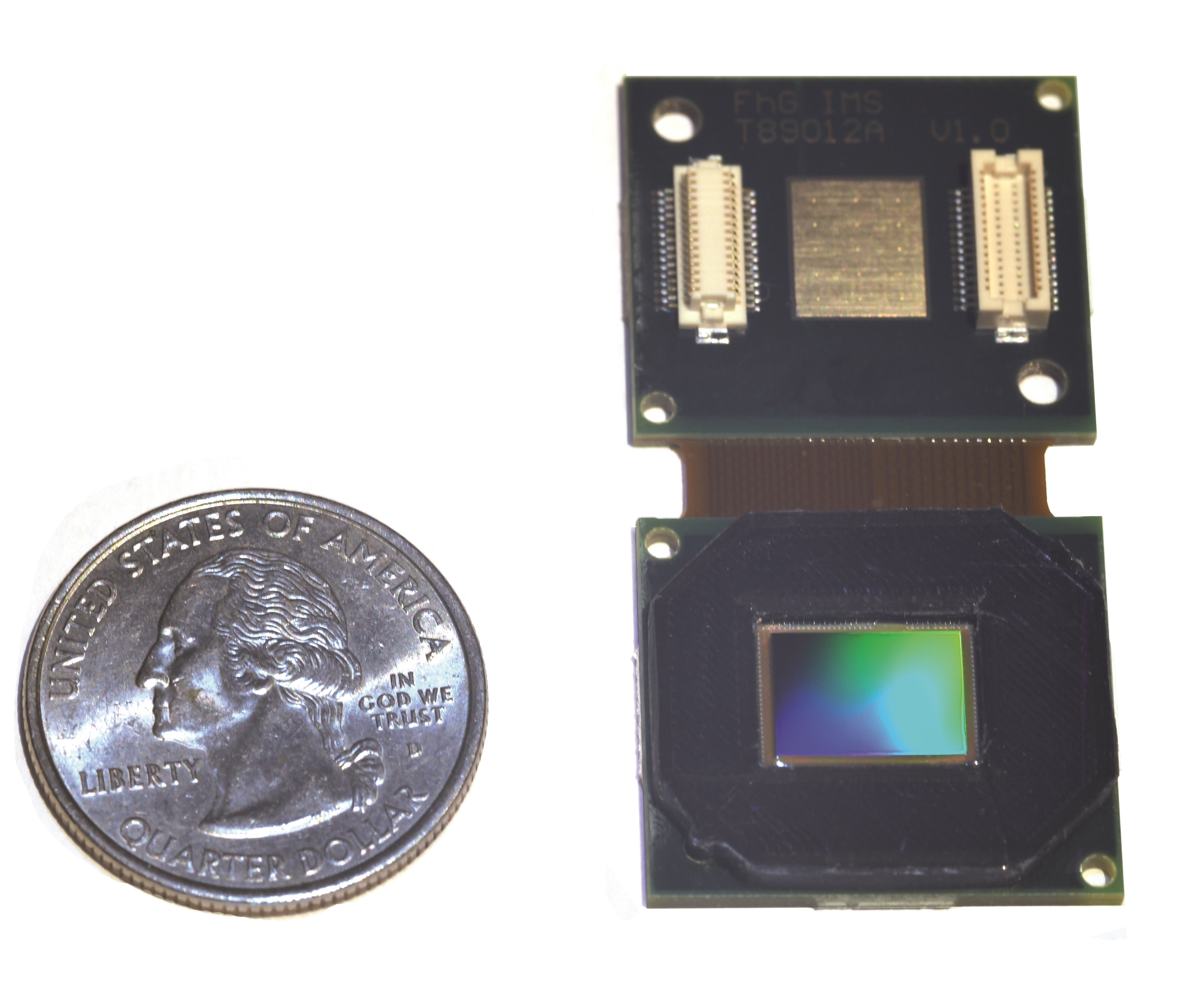
Fraunhofer IMS has realized an infrared line sensor based on its new generation of highly sensitive uncooled infrared sensors with 340 pixels for the LWIR and MWIR range. The number of lines can be digitally adjusted according to customer specifications. Apart from very high temperature sensitivity and dynamics the IR line sensor is characterized by the line frequencies in the kHz range.
Optical line sensors are used in the industry for monitoring and controlling of different processes (e.g. quality control or sorting tasks) in which the objects to be examined are moving along a line. Especially at high advance rates of the objects, the line sensors have advantages over surface sensors, because of their line frequency. Another area of application is spectroscopy.
However, there are processes where optical line sensors in the visible range can’t be applied, because they use, for example, transparent or reflective media, or the quality characteristic is not defined by the surface temperature. Sensors that are not sensitive in the optical range (<800 nm wavelength), but sensitive in the infrared range (wavelengths from 3 μm to 14 μm) are suited for these processes especially. Using the infrared spectral range can often draw conclusions to the materials, which is not possible inside the visible range. Furthermore, the infrared line sensors are well suited for characterization of thermic signatures, for example for monitoring in 3D printing or thermal shaping processes.
Fraunhofer IMS has realized the world’s first infrared line sensor with 340 pixels on the basis of its new generation of highly sensitive uncooled infrared sensors. The number of lines can be digitally configured according to application (2-256 lines). The line frequency of the readout circuit reaches values of up to 7 kHz and is dependent on the configurable number of lines. The underlying 16-bit readout circuit is a fast selection of thermal signals that is even possible in high dynamic range. The high thermal resolution enables detection of temperature differences of less than 60 mK (NETD, frequency-dependent).
