Fraunhofer Institute for Microelectronic Circuits and Systems
TDC for high-resolution time measurement


The high-resolution measurement of time intervals plays an important role. The measurement principle is usually based on the runtime measurement of a sound or light wave. Through this, for the runtime measurements a principally infinite resolution capacity results which is not limited to the resolution of the time measurement. Fraunhofer IMS develops integrated circuits in CMOS technology for application fields that need a high-precision time measurement. So-called Time-to-Digital-Converters (TDCs) can be considered as a very precise stopwatch. They measure the time between a start and stop signal and convert the measured time interval into a digital output value. The resolution is in the picoseconds range. Therefore, TDCs are perfectly suited for precise runtime measurements of sound waves. In the following, several application possibilities of TDCs are presented.
Magnetostrictive position sensor and LiDAR
With a magnetostrictive sensor the position of a mobile permanent magnet is to be determined, which is connected with a solid, acoustic waveguide made of magnetostrictive material. Position sensors that work on the basis of magnetostriction offer several excellent features which are of great importance for the industrial environment. This includes a contactless measurement principle as well as an absolute distance measurement. Through the contactless measurement principle the sensors can be placed in a particular robust and hermetically sealed housing, because the measures position information is transferred via magnetic fields through the housing wall to the sensor. The operating principle is depicted in figure 1.
The permanent magnet can be moved along this waveguide. To measure the distance between the start of the cable and the magnet, a current pulse is fed into the line. This way, a radial magnetic field is generated that is spreading along the line. When this magnetic field reaches the permanent magnet, both magnetic fields overlap and the material of the waveguide is being slightly deformed. Thus, a mechanical impulse is generated that is spreading along the line. This mechanical impulse can be registered by a coil at the start of the line through a change in the magnetization. The change in magnetization leads to a flux alteration inside of the coil and therefore an induced voltage. The runtime measurement itself is carried out by the TDC: it measures the time from feeding of the current pulse to the receiving the resulted mechanical impulse inside the receiver coil. With this time information the position of the permanent magnet can be determined very precisely.
Figure 2 shows the oscillator image of a change in voltage (lower light blue line) received by a sensor, caused by applying a short voltage pulse (yellow line). From the time difference between feeding of the current pulse and the detection of the mechanical impulse the position of the magnet can be determined. In the upper image the distance to the mobile magnet was 14 cm. The distance measurement via light runtime, for example with LiDAR (Light Detection and Ranging), works according to the same principle.
Volume flow measurement
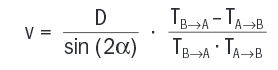
Another application is the measurement of volume flow, for example inside a tube that liquid flows through. The operating principle is shown in figure 3. In the tube is an ultrasonic transmitter and ultrasonic receiver. An ultrasonic pulse is generated at the transmitter which is registered by the ultrasonic sensor. With the generation of the pulse a TDC is started simultaneaously which is stopped as soon as the sensor registrates the pulse. Depending on the application this process is repeated in the reverse direction. The time needed by the impulse to get from the generator to the sensor depends on the flow velocity of the fluid and the direction of the impulse. Through a runtime measurement with a TDC the respective runtimes T of the impulse can be determined and therefore statements to the speed and flow direction of the volume flow can be made under consideration of the dimensions of the tube: